This is a guest post by Bob Warfield, founder of the popular CNCCookbook blog and author of G-Wizard, the leading feeds and speeds calculator.

In this second part of the multi-part series of guest posts, I want to walk you through the basics of feeds and speeds.
In the first part of this series, I introduced you to the basics of determining the speeds part of your feeds and speeds for CNC. As you’ll recall, “speeds” is how fast to spin the spindle in rpms, and “feeds” are how fast to feed the cutter into the work. In that first article, I alluded to the idea that it takes a harmonious combination of feeds and speeds to produce the best results. To explain how the two interact, I want you to get familiar with the idea of Feeds and Speeds Sweet Spots. Just as a reminder, if you want to dig more deeply into Feeds and Speeds after this series finishes, or if you’re curious about more advanced topics or even just particular topics I haven’t covered, check into CNCCookbook’s in-depth Free Feeds and Speeds Course. It’s a great resource for you, and we have a number of other Free Online CNC Training Courses too.
As I mentioned, it is the interaction of Feeds and Speeds matched to each other that determines how the cut will turn out. But how does that work?
The best way I’ve found to explain this is to use the idea of Feeds and Speeds Sweet spots. I like to draw them pictorially like this:
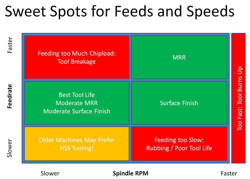
Let’s try out a few examples to see how this works.
Say we’re running at a rate that is producing fantastic MRR’s. BTW, MRR is the machinist’s abbreviation for Material Removal Rate. When you’re roughing out a part, you want to focus on getting the highest MRR’s, all other things being equal, because that means you’re removing material as efficiently and quickly as possible. Now, we’re done roughing, and we want to know how to modify our Feeds and Speeds for a better finish on the part. The feeds and speeds that remove material fast are not necessarily gentle, and the marks left in the material can sometimes look like an angry beaver took out all it’s frustrations by chewing through!
Looking at our Sweet Spot diagram, to go from the best Feeds and Speeds for MRR, we should keep the spindle rpms about the same but reduce the feedrate. If you visualize the cutter, it has let’s say 2 flutes, each a cutting edge. It spins around and takes 2 bites of the material each revolution of the spindle. The size of the bite is controlled by how far the cutter is pushed during the bite. So if we slow the feedrate, we’re going to push the cutter less far so it will be taking smaller bites. It only makes sense that a smaller bite results in a better finish, right?
Now suppose we’re at that ideal MRR, but we decide to slow down the spindle. Maybe we think the cutter is getting to hot and slowing down the spindle will lead to longer tool life. Be careful!
We can see that as we slow it down more and more, we will move from the MRR sweet spot into a read zone:
Feeding too Much Chipload: Tool Breakage!
That sounds bad, but how did it happen and what does it mean?
Essentially, if we keep the same feedrate, but slow down the spindle rpm, we’re pushing the cutting edge further through the material on each bite forcing it to swallow more material. The amount it swallows is called the “Chipload”. If you could pick up a chip, flatten it, and measure its thickness with a micrometer or calipers, you’d find the chipload is the thickness of each chip.
Feeding too much chipload is bad, just like trying to force too much food when you eat. Eventually, there’s so much food that when you try to swallow you choke. When the chips are being sliced, they have to fit between the flutes until the cutter’s helix can carry them up and clear of the cut. BTW, those special “downcut” cutters for CNC Routing tasks? They’re pushing chips down into the cut, so it can be even harder for those chips to get clear. If there’s too many chips they choke and jam the cutter flutes and you’ll snap the cutter right off pretty quickly.
Because this can happen very suddenly, never reach out and slow down your spindle while feeding. It’s always better to slow the feedrate then slow the spindle rpms.
One more thing about jamming up flutes–the fewer the flutes, the more room is available for chips. Some materials, such as aluminum, require you to use 2 or 3 flute cutters. A 4 flute, unless you know some advanced tricks, is going to jam in most cuts. The reason is that the chiploads for aluminum are high–you can take big slices, and because of the way the chips curl, they use up the space between flutes in a hurry. Hence they need more space. A 1 flute cutter has the most space of all.
How about a happy low stress medium?
That’s the green area marked “Best Tool Life, Moderate MRR, Moderate Surface Finish.” That’s an ideal spot for many hobbyists, especially beginners to aim for.
You might have heard folks talking about rubbing, what does it mean?
Here’s one of those counter-intuitive things about machining–if you slow the feedrate too much, and especially if you slow the feedrate on shallow cuts, you’ll cause it to rub and this is one of the worst things for tool life.
Here’s why:
Think of the cutting edge. At some scale, probably microscopic, what feels like a sharp pointy edge, actually has a radius. You can’t make tools infinitely sharp, and at some magnification, they look dull. Now check out this illustration:
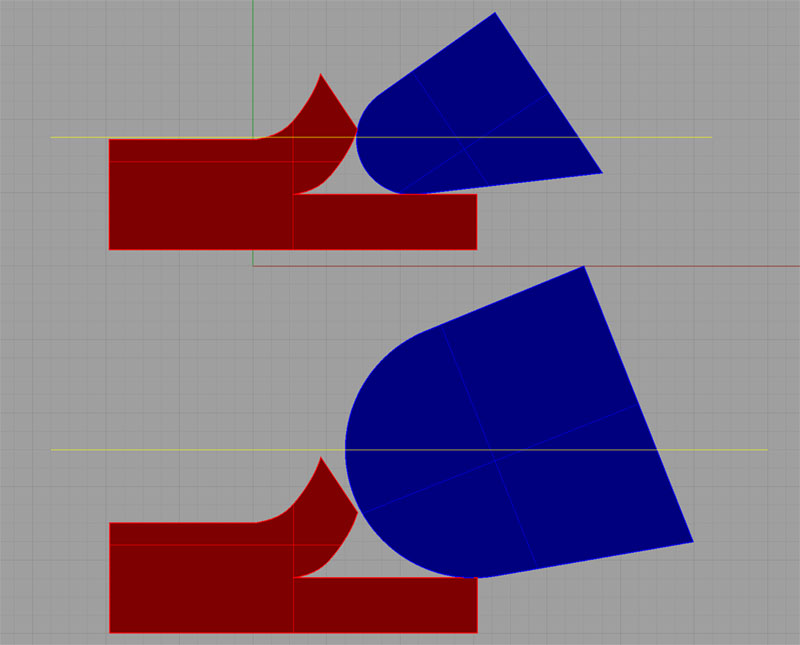
Rubbing when there’s too little chipload…
Visualize the center of the radius of the cutting edge as the yellow line. The top picture shows the yellow line down at the surface of the material or ideally even below that surface. When that happens, the cutting edge is getting down under the material and cleanly slicing off chips.
But, if the chip is too thin, the yellow line is too high and the cutting edge can’t slice under the chip. Instead, it plows along the top, and the underside of the radius is doing more rubbing than slicing. It’s got to gouge out a chip almost by friction alone. This results in a lot of heat being generated both in the cutter and in the material. If you’re cutting wood, you may smell smoke or see the wood blacken from heat. It can get hot enough to catch fire even.
Now can see that when you thought you were taking it super easy on your cutter with light cuts, you were actually causing rubbing, the tool was getting way too hot, and it’s life was very short indeed.
But it gets worse, because if your Cut Width is too small, you might also have triggered what’s called Radial Chip Thinning.
When I think about Radial Chip Thinning, I am always reminded of the scene from Alice in Wonderland where Alice is running as fast as she can with the Red Queen and getting nowhere:

“Well, in our country,” said Alice, still panting a little, “you’d generally get to somewhere else—if you run very fast for a long time, as we’ve been doing.” “A slow sort of country!” said the Queen. “Now, here, you see, it takes all the running you can do, to keep in the same place. If you want to get somewhere else, you must run at least twice as fast as that!”
We’ve got our arms around the idea of chipload, and that if we go too slow, the cutter rubs instead of slicing, so we have to keep the chipload higher than the cutter’s edge radius. But, there is a geometric effect called Radial Chip Thinning that makes that harder. Let’s visualize our cutting edge slightly differently:
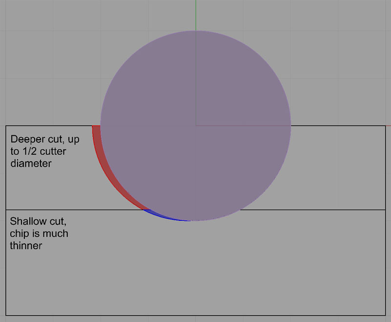
Due to Chip Thinning, Shallower cuts maker thinner chips than expected…
Given the way things work, chips do not have a cross section of equal thickness. They start thin and get thicker–it’s just how the cutter moves through the material slicing.
The thinnest part of the chip is on the bottom. But what if we are taking a very shallow depth of cut? Say we’re only taking 10% of the cutter diameter as our depth of cut? If we do that, we mostly just get the thinnest part of the chip–the blue part in the diagram and none of the red.
Can you see where this is going?
By deciding to be super conservative and taking a very light cut, we’re getting a unusually thin chip. And guess what? We’re going to be right back to rubbing, if it is thin enough, even though we’re feeding at a rate that shouldn’t lead to rubbing!
Talk about best laid plans... what can we do about Radial Chip Thinning?
Well, the answer is we must artificially speed up our feedrate to account for it and produce thicker chips to avoid the rubbing. Incidentally, if you read most simplified articles about Feeds and Speeds, they’ll give you a basic set of formulas that relate feeds and speeds and tell you how to calculate chiploads and so on. It all looks easy. But a simple geometric phenomenon like Chip Thinning can make those simple formulas wrong in a heartbeat. There are more formulas available to tell you exactly how much to speed things up to avoid chip thinning, or you can just always make sure cuts are deeper than 1/2 the cutter diameter–no chip thinning to worry about unless you get below the 1/2 number. But often they don’t tell you these things in the simple explanations.
I started out with the simple formulas a long time ago. I had them in an Excel spreadsheet. I steadily added more formulas as I learned about things like Radial Chip Thinning. There are actually quite a few phenomena like Chip Thinning to consider. What I eventually decided was that good Feeds and Speeds require a lot of calculations. You can try to keep things simple and be conservative, but as we’ve seen, sometimes being too conservative can lead to rubbing and chip thinning and actually makes things worse. In the end, juggling all the variables and formulas proved too much for my Excel spreadsheet, and I was prompted to create the very first G-Wizard Calculator. Today’s version is even more comprehensive – it considers over 60 variables quickly and automatically so you don’t have to worry about them.
Whether you’re a beginner or a pro, I highly recommend Feeds and Speeds Calculators. Get a good one. They’re not very expensive compared to the cost of a cutter or the cost of being frustrated about how to get better results from your CNC.
You’ve got a good grounding of the basics. You’ve heard and hopefully understand quite a few new terms.
Here’s a handy glossary of basic feeds and speeds terminology too
You’ve got the Sweet Spot diagram to help you understand where you are and what happens if you increase or decrease feeds or speeds from that point.
In the Next Installment, I’m going to give you a bunch of Handy Feeds and Speeds Tricks. These are ways to solve problems like discovering your CNC machine’s spindle won’t turn at slow enough rpm’s to get to a sweet spot. They’ll be very handy to have in your tool kit and will save a lot of frustration.
See you again soon!
We'll keep you up to date on new things in the world of Carbide 3D, and CNC in general.