Assembly
80mm Water-Cooled VFD Spindle
Contents
- 80mm Spindle Mount w/ Dovetail Mount
- 4 x M6x35 Socket Head Cap Screws
- 2 x M6x20 Socket Head Cap Screws (clamping bolts fitted)
- 80mm Water-Cooled Spindle
- Enclosed 220V VFD
- VFD Power Cable (L6-20 Plug for 220v)
- Communications Cable
- Spindle Cable, 6m
- Shapeoko 5 Pro Gas Strut Kit
- Sweepy 2.0 (80mm)
- ER-20 Collets & Nut
- 1/8" Collet
- 1/4" Collet
- 1/2" Collet
- ER-20 Collet Nut
- CW3000 chiller and power cable
- Wrench, 30mm for the collet nut
- Wrench, 21mm for the shaft
- 2 x 8mm OD Water Coolant Line (7.5m long)
Shop Requirements
- Shapeoko 5 Pro
- A computer running the latest version of Carbide Motion 6.
- 220v outlet for VFD - L6-20 receptacle
- 110v outlet for CW3000 - Standard US receptacle, NEMA 5-15
Tools and Consumables Required
- Carbide 3D Shapeoko tool kit (assorted hex wrenches)
- Adjustable Wrench
- Flathead screwdriver for opening the drag chain links
- 9L of coolant
Environmental Requirements
The spindle is intended for operation above 15 °C (59 °F). In cooler conditions, perform a warm-up cycle before applying any load or starting cutting operations.
Remove Existing Router or Spindle
- Power on the Shapeoko and connect to it through Carbide Motion.
- Initialize the machine.
- Jog the machine gantry to the front of the table for easy access to the Z-axis.
- Turn off the machine.
- Unplug the current router/spindle from the power outlet.
- Using a 5mm hex key, loosen the two M6x20 bolts on the spindle mount's right side.
- If upgrading from a 65mm spindle - support the spindle from below to ensure it does not drop through.
- Remove the current router/spindle by lifting it through the top of the spindle mount.
- Using a 5mm hex key, remove the four M6x35 bolts securing the spindle mount to the Z-axis.
- Remove the Left Gantry End Cap by loosening and removing two M6 socket head screws. (Shapeoko 5 Pro Only)
- Using a 2.5mm hex key, remove the eight M3x6 socket head screws that secure the left-side Y-axis and rear-most X-axis drag chain. The bolts are located on the left Y carrier plate, left Y rail/limit switch mount, left X extrusion, and rear X/Z drag chain bracket.
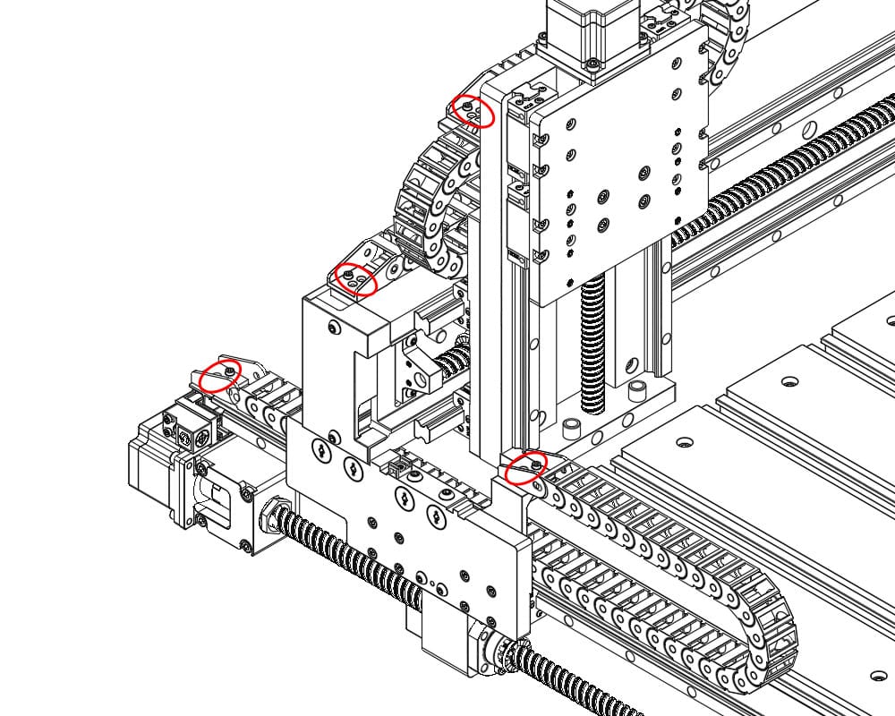
- Remove both Y left and rear X rear drag chains from the machine.
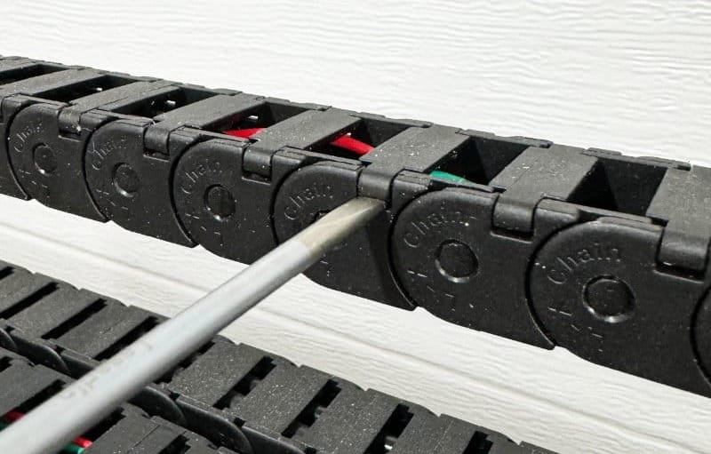
- Open all drag chain links using a flathead screwdriver.
- Insert the screwdriver tip underneath one end of the link cover, approximately 1/16" or 1.5mm deep, and twist gently to pop the cover open.
- Remove the spindle/router cable from the drag chain.
Install - Shapeoko 5 Pro Gas Strut Kit
Please refer to the Gas Strut Kit Assembly guide
Install - Spindle Mount and VFD Spindle
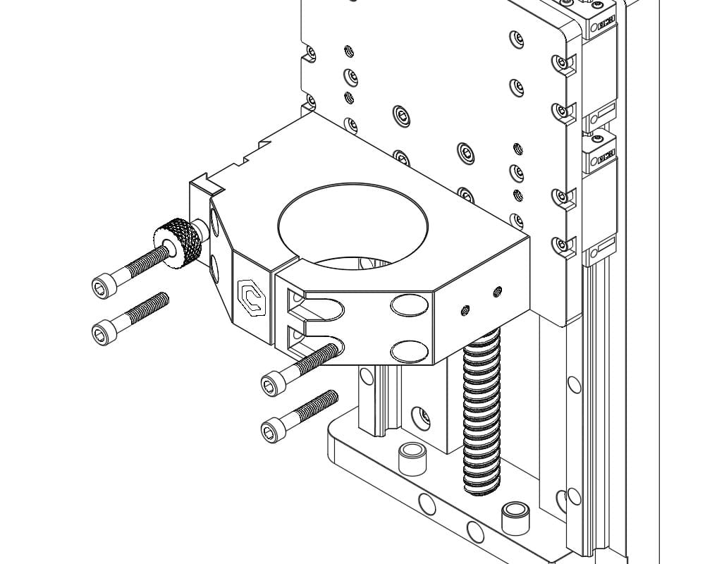
- Align spindle mount with Z-axis front plate. The 80mm mount sits higher than the 65mm mount, allowing for greater tool clearance and adjustability for the dust shoe. The mount should be aligned with the top four M6 holes, near the center of the Z-axis front plate.
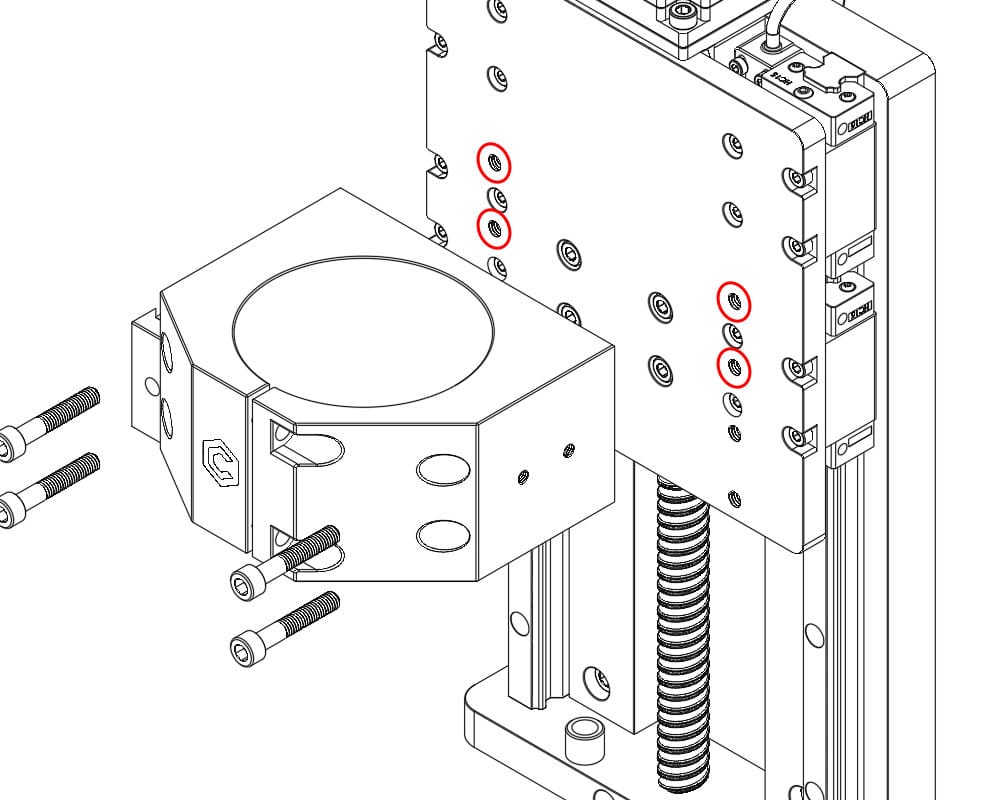
- Secure the spindle mount using a 5mm hex key using four M6x35 bolts.
- Do not exceed 10N·m of torque.
- The dovetail feature should be on the left side.
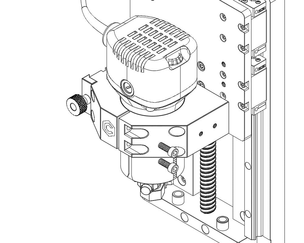
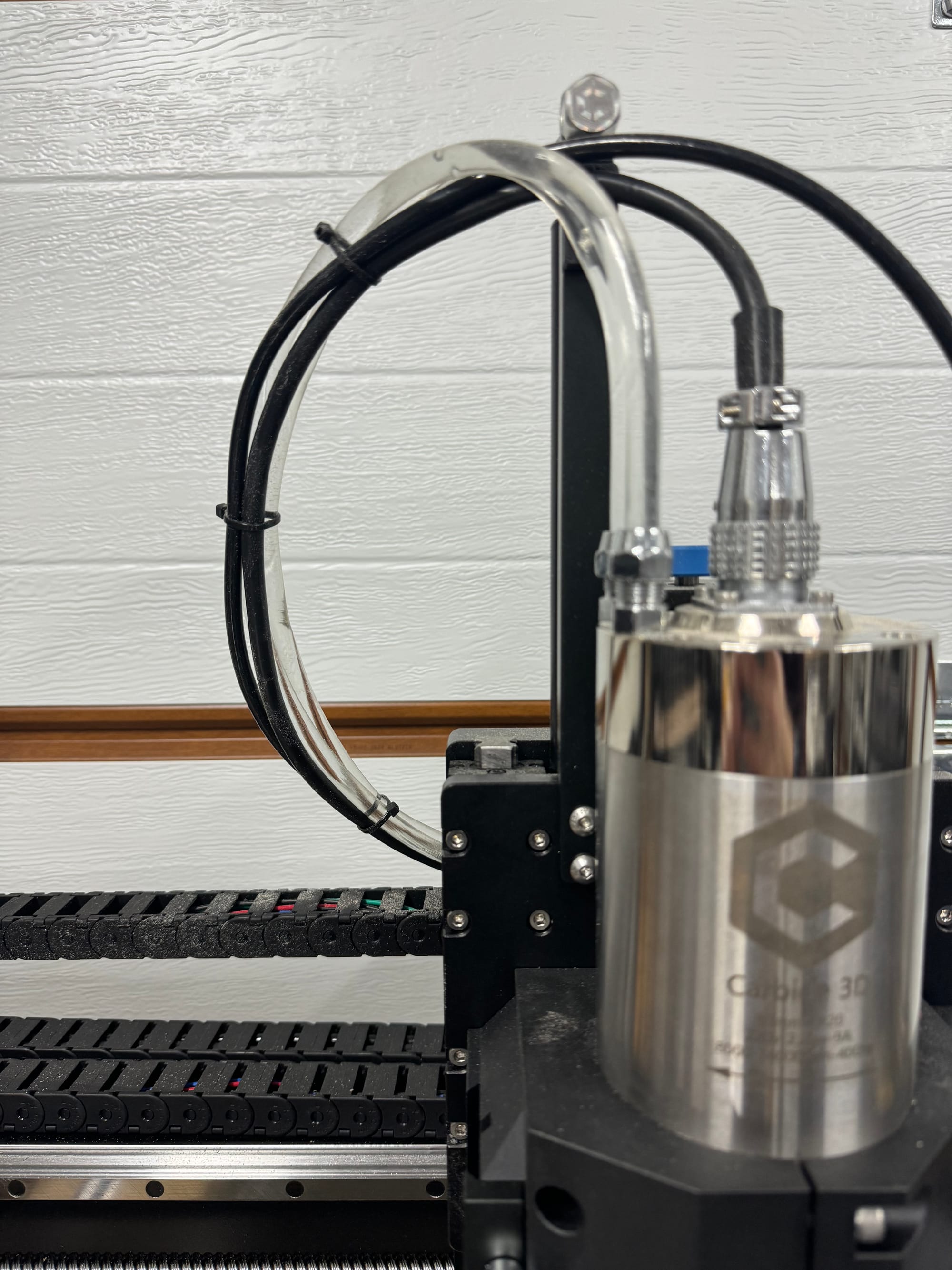
- Lower the VFD spindle into the mount from above.
- The C3D logo and informational decals should facing forward. The height of the spindle can be adjusted based on user requirements.
- With the VFD spindle positioned at the desired height, tighten the two M6x20 clamping bolts on the right side of the spindle mount, securing the spindle in place. Do not exceed 10N·m of torque.
Install - Wiring & Coolant Lines (Gantry Drag Chain)
- With the drag chain removed and links open, lay the spindle cable and water coolant lines in the drag chain.
- Ensure the threaded spindle connector is on the side of the drag chain that terminates at the Z-axis.
- Leave 65cm of spindle cable and water coolant line free on the Z-axis side of the drag chains.
- Snap the drag chain links closed.
- Using a 2.5mm hex key and four of the M3x6 bolts (previously removed) secure the X rear drag chain to the left X axis mounting point and rear Z/X drag chain mount.
- Check for any kinks or sharp bends that could restrict water flow.
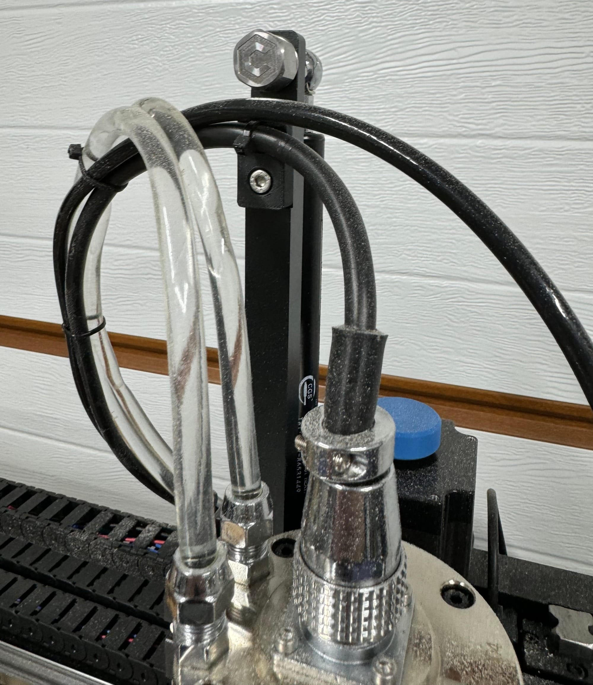
- Plug the aviation-style connector into the top of the spindle. Screw the collar clockwise to secure.
- Remove the two compression nuts from the spindle's coolant ports.
- Slide each compression nut onto a length of coolant line.
- Press the coolant line onto the coolant fittings. If needed, the end of the coolant lines can be warmed in hot water to increase flexibility.
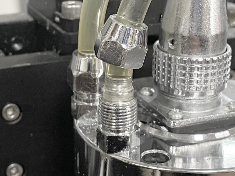
- Tighten the compression nuts with a small adjustable wrench until moderate resistance is felt. The compression nuts do not need to bottom out on the threads in order to create a seal, over-tightening may damage the hose.
- Secure the spindle cable and the coolant lines as a single bundle using cable ties.
- Secure the spindle cable to the Shapeoko 5 Pro Gas Strut Kit
Install - Wiring & Coolant Lines (Gantry to Y-Axis Transition)
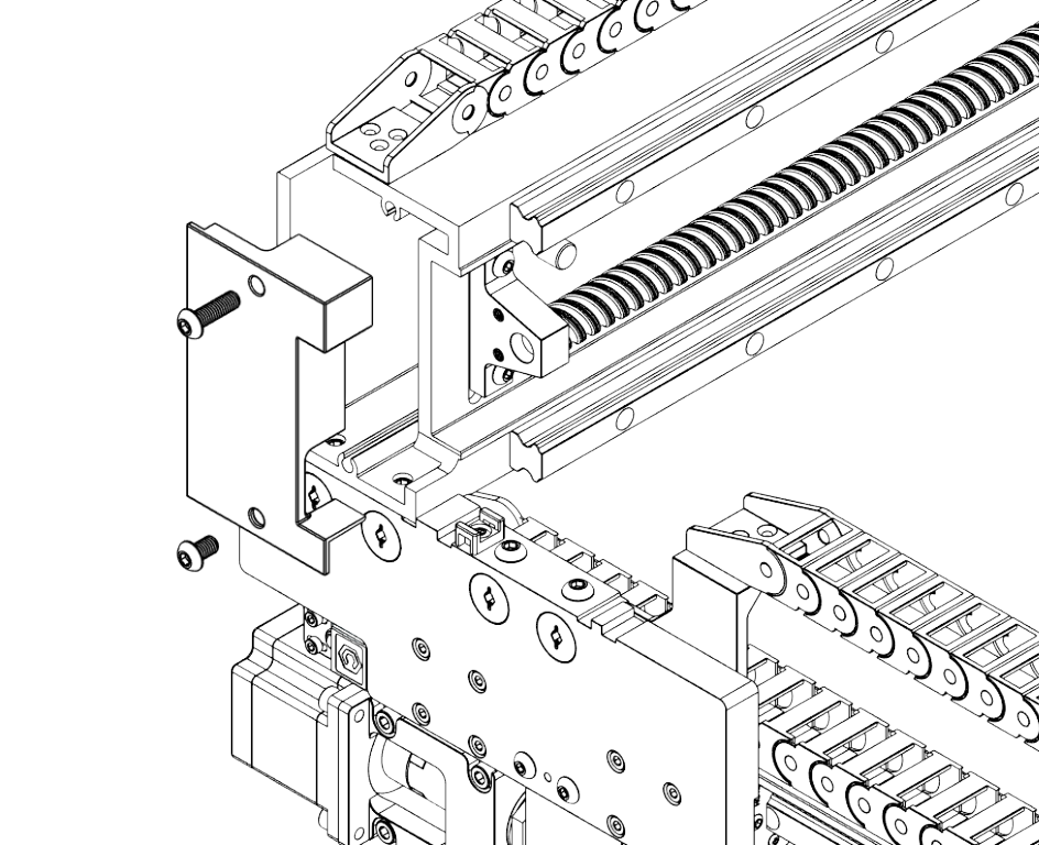
- Using a 5mm hex key, remove the black plastic end cap on the left side of the gantry by removing the top M6x30 and lower M6x12 bolt.
- Carefully run the spindle cable inside the left gantry end cap.
- Replace the end cap and bolts.
- Water coolant lines should run outside the gantry end cap and transition to the left side drag chain.
- DO NOT feed the coolant lines through the gantry end cap as this could hide a pinched or kinked hose.
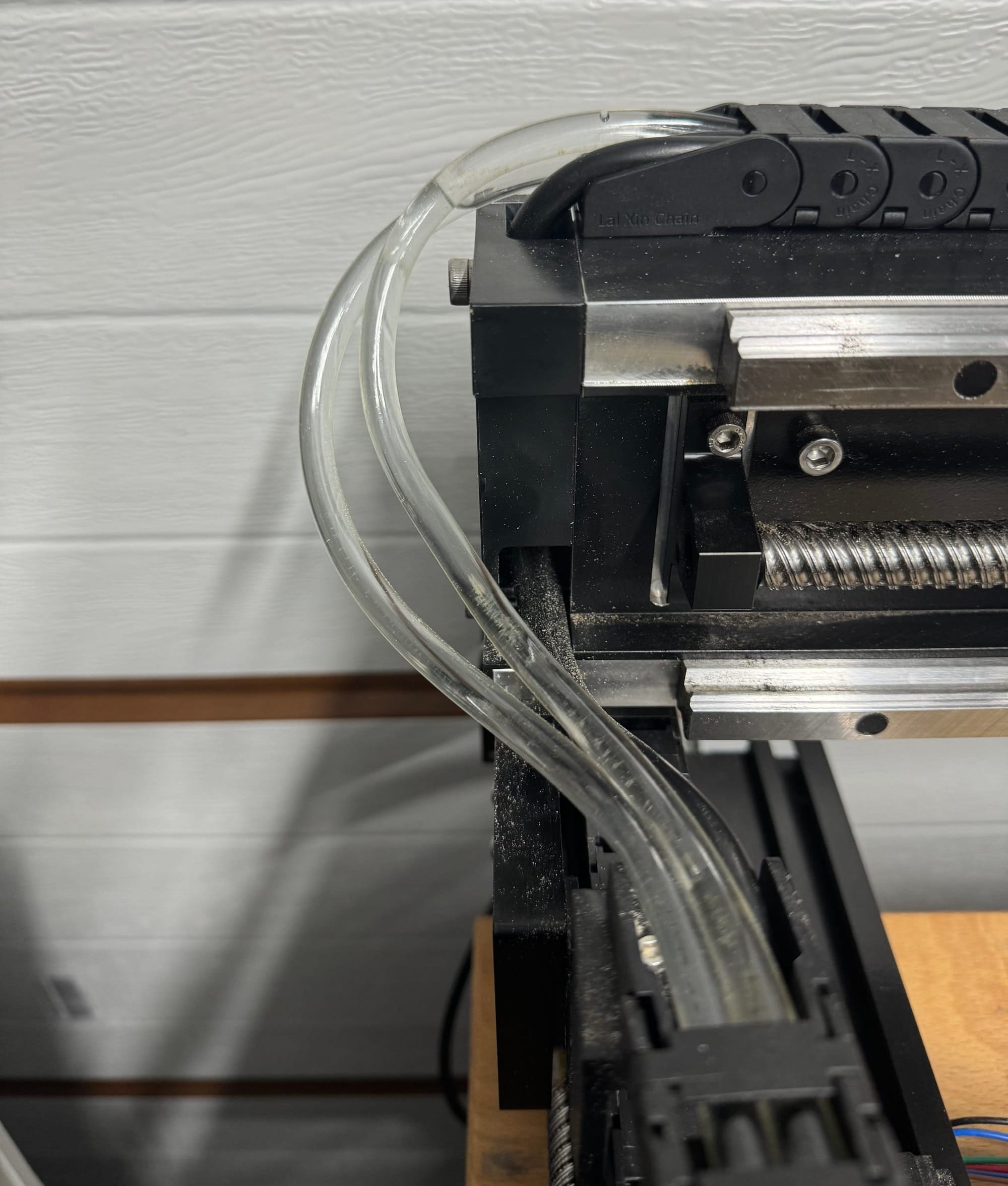
Install - Wiring & Coolant Lines (Y-Axis Drag Chain)
- With the drag chain removed and links open, feed the spindle cable and water coolant lines into the drag chain. Close every five links to secure the cable and lines loosely.
- Secure the top of the drag chain to the Y left plate using two M3x6 socket head screws (previously removed). Adjust the cable and water lines to ensure flexibility.
- Secure the rear of the drag chain to the rear left mounting point using the remaining two M3x6 screws.
- Close the remaining drag chain links.
- Check for any kinks in the hose that might restrict coolant flow.
CW3000
The CW3000 is a recirculating chiller. It will bring the coolant temperature down to ambient levels.
It should be placed away from dust and debris (ex. under or beside the Shapeoko). Approximately 30cm (1 foot) of clearance should be maintained around the unit for best performance.
Connecting and using the CW3000
- Feed the two coolant lines from the left side drag chain to the chiller, avoiding any kinks or sharp bends that could restrict flow.
- Plug each coolant line into one of the push-fit connections on the rear of the CW3000. The order is not important.
- Gently tug on each coolant line to ensure it is securely locked in place.
- Plug the power cable (C13 end) into the receptacle at the rear of the CW3000, plug the other end into a wall outlet, and toggle the power switch by the receptacle on the back of the CW3000 to ON.
- Note: The CW3000 runs on 110v, not 220V.
- To operate the CW3000, use the switch located on the front panel to turn it on and off.
- The CW3000 should always be turned on before running the spindle.
- If unusual discoloration is observed in the spindle coolant lines, drain the CW3000 reservoir using the drain valve on the rear. Flush the system to clear out any microbial or algal growth and re-fill the reservoir with appropriate coolant.
Filling the CW3000
- To fill, remove the cap on the top of the CW3000.
- This unit can accept 9L of coolant.
- Fill the CW3000 with one of the following:
- General-purpose automotive mono-ethylene glycol-based coolant (anti-freeze), diluted to a 50/50 concentration with distilled water.
- Windshield wiper fluid can also be used but should be diluted to spec.
- Note: Coolant mixture must be diluted down to at least 50% concentration. A mixture that is too rich will not trigger the flow sensors and lead to a low flow alarm on the CW3000. If this happens, drain approximately half a liter of coolant from the chiller and replace with an equal volume of distilled water.
- Replace the reservoir cap.
- Run the CW3000 for several minutes to purge air from the system and check for any leaks at the connections between the machine, hoses, and spindle.
Mounting the VFD
- The VFD unit should be placed somewhere sheltered from dust and debris.
- The VFD unit should be positioned for easy access. You should be able to easily operate the spindle lockout button on the enclosure.
- The area around the VFD enclosure should be kept clear of anything that could hamper ventilation, particularly on the sides of the enclosure that are vented. We recommend maintaining a separation of 30 cm (about 1 foot) between the VFD and any obstructions.
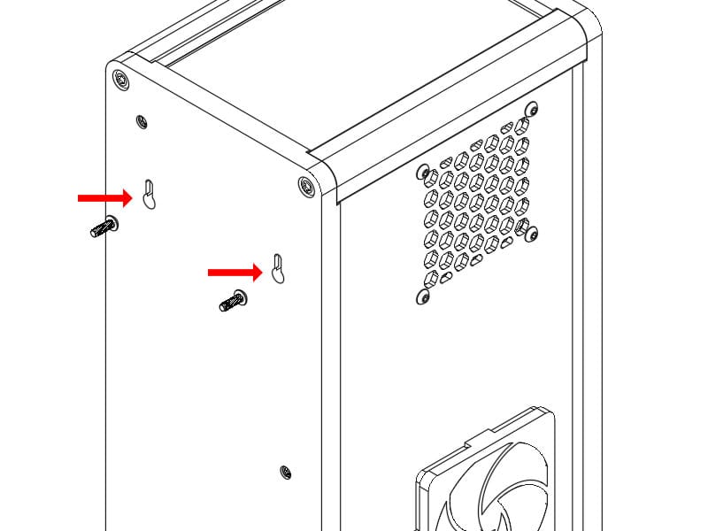
- The VFD enclosure can optionally be wall-mounted. There are two slotted holes spaced 85mm apart that can be used to hang the unit.
Connecting the VFD to Shapeoko
- With the Shapeoko powered off, plug one end of the communication cable into the Spindle port on the Shapeoko controller.
- On Shapeoko 5 Pro, there is an adapter cable that needs to be used between the communications cable and the controller.
- Plug the other end of the communications cable into the 6-pin port on the left side of the VFD enclosure.
- Plug the C13 end of the power cable into the receptacle on the VFD enclosure's right side.
- Plug the other end of the power cable into an L6-20 receptacle.
- Flip the power switch on the VFD Enclosure, next to where you plugged in the power cable.
Configuring Carbide Motion
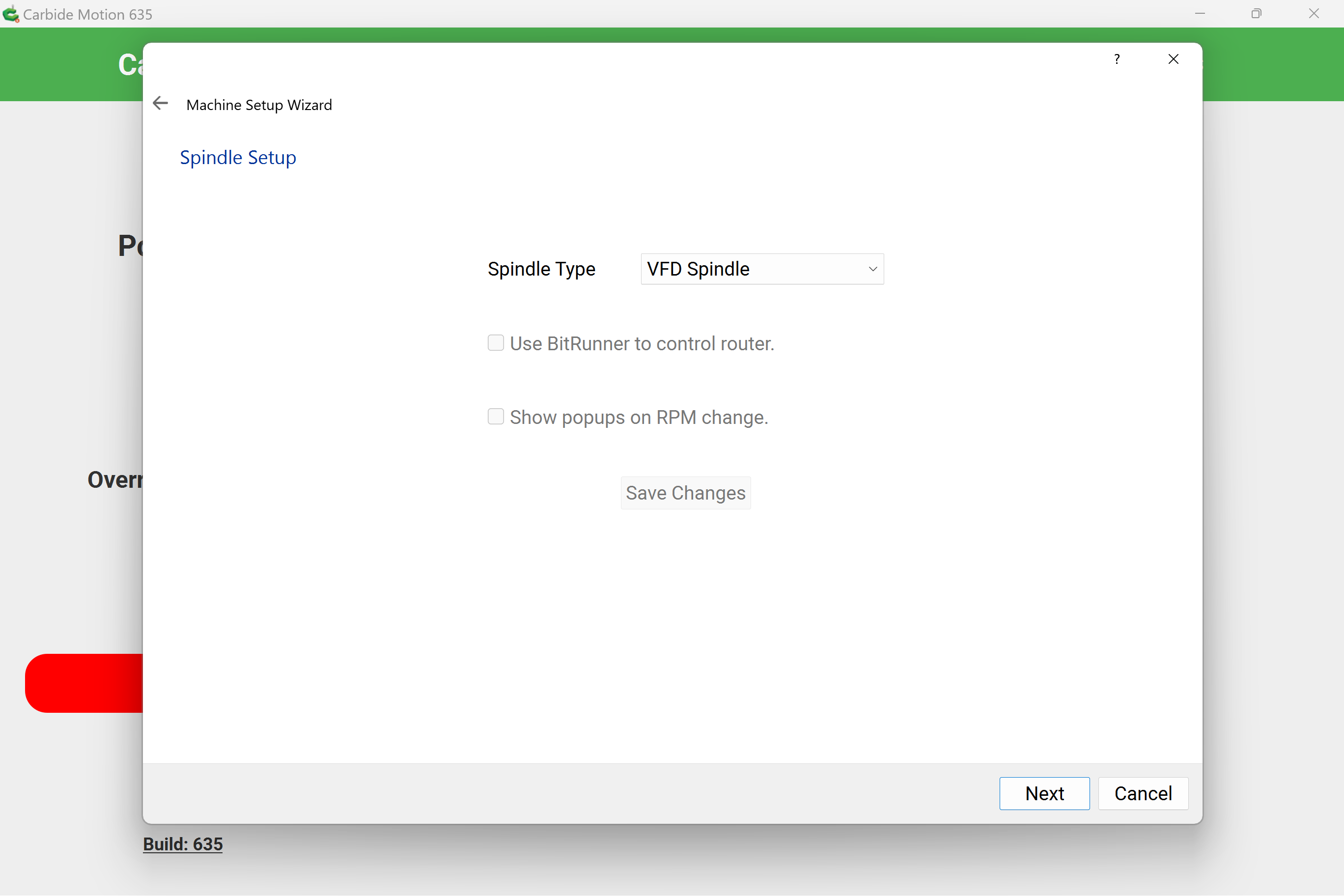
- In order for your Shapeoko to communicate with the VFD correctly, you will need to run the New Machine Setup Wizard.
- When prompted for the type of spindle being used on your CNC, select VFD Spindle
Operating Your VFD Spindle
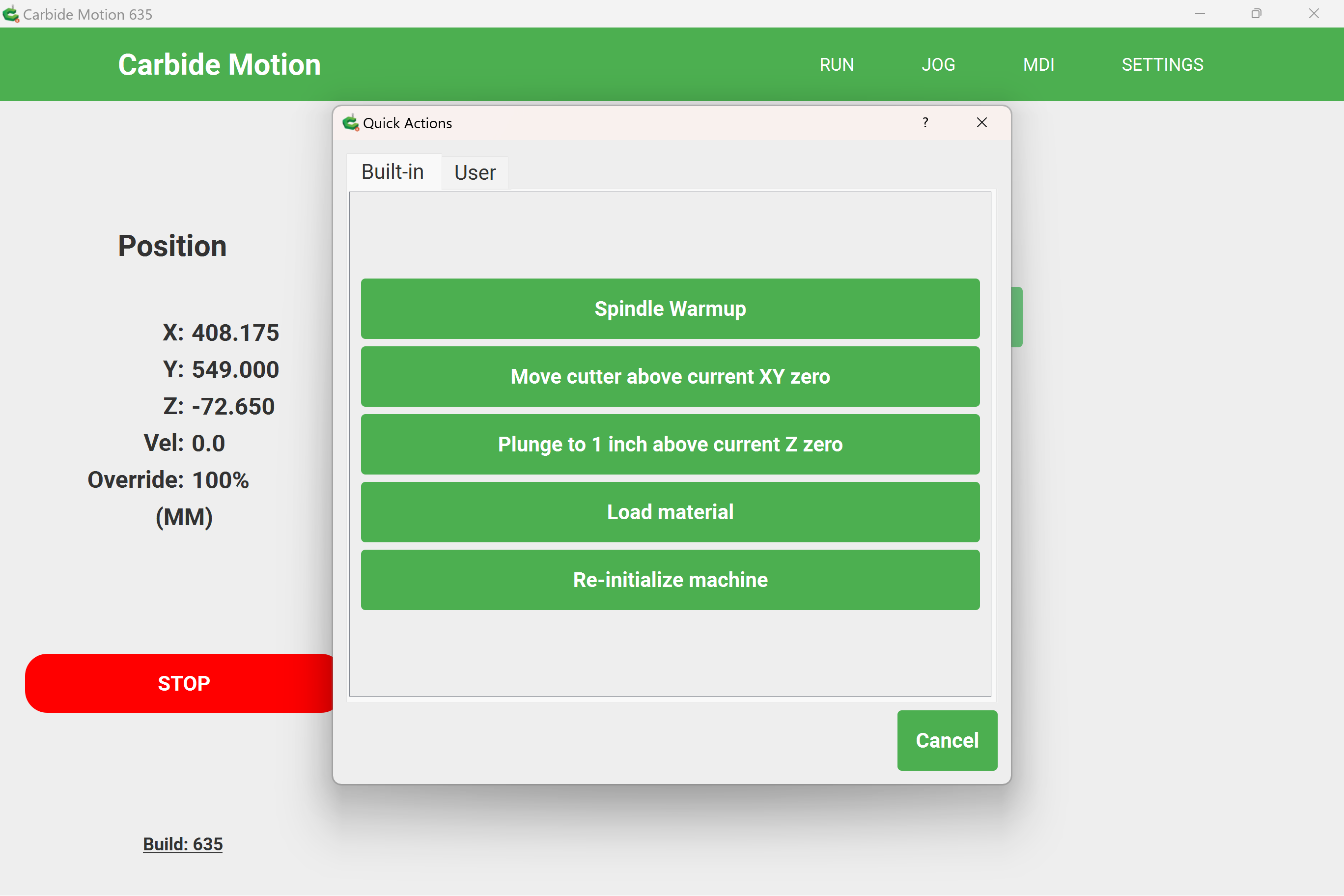
- Before performing any cuts with the VFD Spindle, you should run a warm-up cycle. This is also recommended if the machine has been sitting idle for more than 2 days and/or if the ambient temperature is below 15°C/59°F.
- You can run a built-in warm-up cycle through Carbide Motion's Quick Actions menu.
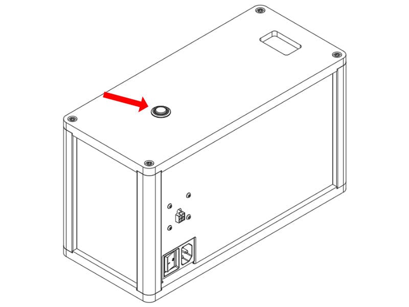
- The Spindle Enable button on the front of the VFD controller disables the spindle. This can provide an additional layer of safety when you are interacting with the spindle (ex. changing and endmill), or be used to ensure the spindle does not run when using tools like drag engraving tools or drag knives.
- If the Spindle Enable button is on (illuminated), the VFD is ready to run. If it is off the spindle will not activate, even if commanded to in a program.
Caring for Your VFD Spindle
Please refer to the VFD Spindle Care & Maintenance guide
FAQ
What do these VFD error codes mean?
Below are common codes and errors - this list is periodically updated by support. Please email support@carbide3d.com if any of these error codes cannot be resolved.
- Err01 - Over-current detection. Check cables for proper connection and verify wall outlet voltage is 220V +/- 10%
- Err04 - High voltage. Ensure wall outlet voltage is 220V +/- 10%
- Err08 - Low voltage. Ensure wall outlet voltage is 220V +/- 10%
- Err31 - Current fault detected. Check wiring between spindle and VFD
Do I need a flow monitor?
No - The CW3000 will show error E0 if there is a problem with coolant flow.
What are the specifications of the CW3000?
- 49 x 27 x 38 cm (L X W X H)
- Power draw 1A @ 110V.
- Flow rate - 10L per min
- Reservoir capacity - 9L
What do these CW3000 error codes mean?
- E0 - Poor flow detected.
- Ensure there are no blockages or kinks in the coolant hoses. Also ensure that your coolant is appropriately diluted. An incorrect concentration may not register on the built-in flow sensor.
- E1 - Coolant Temperature High
- Ensure ambient temperatures are within recommended bounds (below 30°C/86°F) and allow some time for the CW3000 to reduce the temperature of the coolant.