Accessories
Air Assist Kit
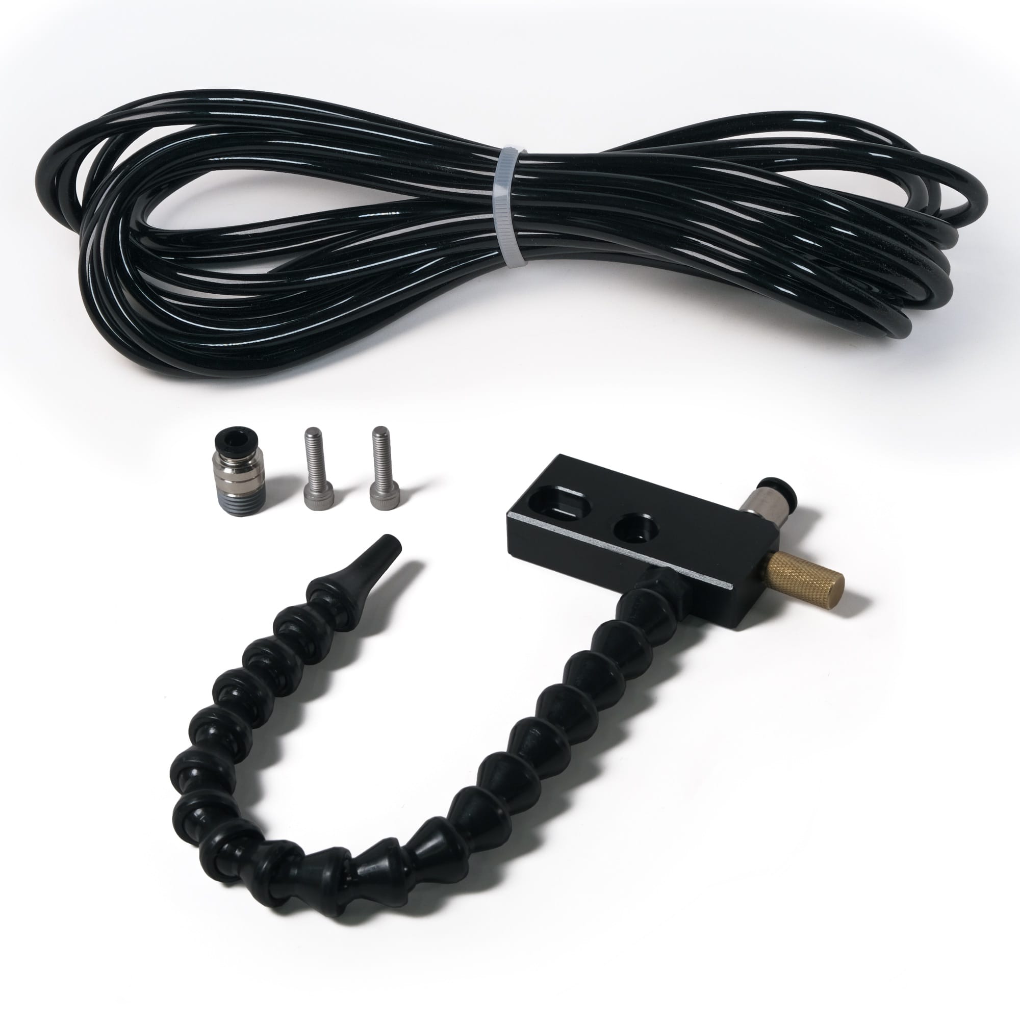
Contents
- Air Assist Unit
- 30 cm of Modular Hose with Nozzle
- 6mm Polyurethane Tubing (6m length)
- 6mm - 1/4 NPT Fitting
- 2 x M5x20 Socket Head Cap Screws
- Mating Plate
Tools required
- Carbide 3D Shapeoko Tool Kit (metric hex wrenches ranging from 1.5 to 5mm)
- Flat Head Screw Driver
- Adjustable Wrench
Compatibility
The Air Assist Kit is designed for integration with the heavy duty (HD) spindle mounts of the Shapeoko 4, Shapeoko Pro, Shapeoko 5 Pro, and Shapeoko HDM.
Shop Requirements
The Air Assist Kit requires an external supply of compressed air. The air delivered to the air assist unit should be dry and regulated to between 15 to 45 PSI. The Air Assist Kit should not be connected directly to a compressed air supply in excess of 45 PSI (3 bar).
The compressor used should be able to deliver at least 2 CFM (56L/min) of air continuously at the desired operating pressure (3 CFM preferred, please check the compressor's rated duty cycle and performance prior before purchase). It should also have a 6 gal. (22L) minimum tank to buffer against pressure changes during operation.
Assembly Instructions
Step 1 - Prepare Machine for Installation
- Bring the gantry to the front of the machine for easy access. On a Shapeoko 5 Pro this requires the machine to be powered on.
- Power on the Shapeoko and connect to it through Carbide Motion.
- Initialize the machine.
- Jog the machine gantry to the front of the table for easy access to the Z-axis.
- Turn off the machine.
Step 2 - Add Tubing to Drag Chains
- Remove the Left Gantry End Cap by loosening and removing two M6 socket head screws. (Shapeoko 5 Pro Only)
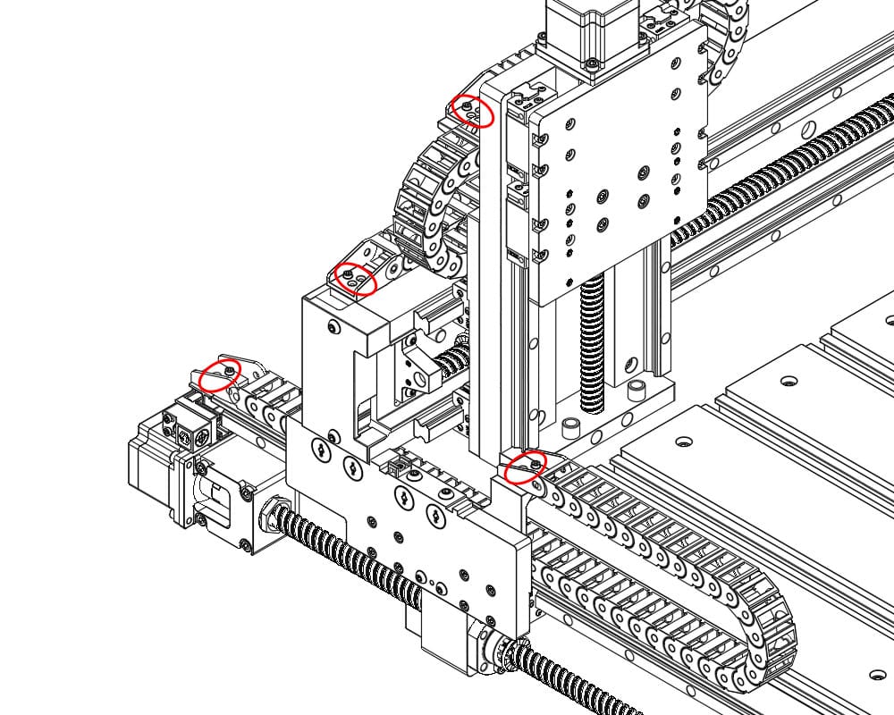
- Remove the drag chains that guide the spindle power cable. These are the left side Y-axis drag chain and rearmost X-axis drag chains on the machine.
- Using a 2.5mm hex key, remove the eight M3x6 socket head screws that secure the left-side Y-axis and rear-most X-axis drag chain. The bolts are located on the left Y carrier plate, left Y rail/limit switch mount, left X extrusion, and rear X/Z drag chain bracket.
- Open all drag chain links using a flathead screwdriver.
- Insert the screwdriver tip underneath one end of the link cover, approximately 1/16" or 1.5mm deep, and twist gently to pop the cover open.
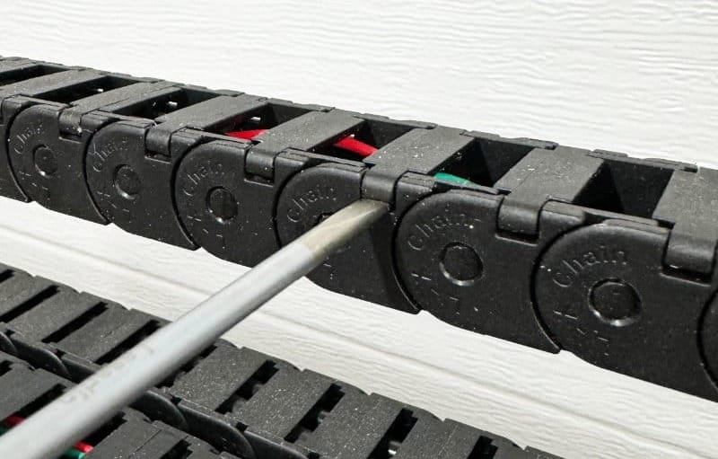
- Lay the 6mm tubing in the drag chain and close the covers.
- Ensure there is at least 28" (70cm) of extra tubing protruding on the spindle-side of the drag chain set.
- Reinstall the drag chains along the Y-axis and Gantry, reversing the process performed earlier in Step 2.
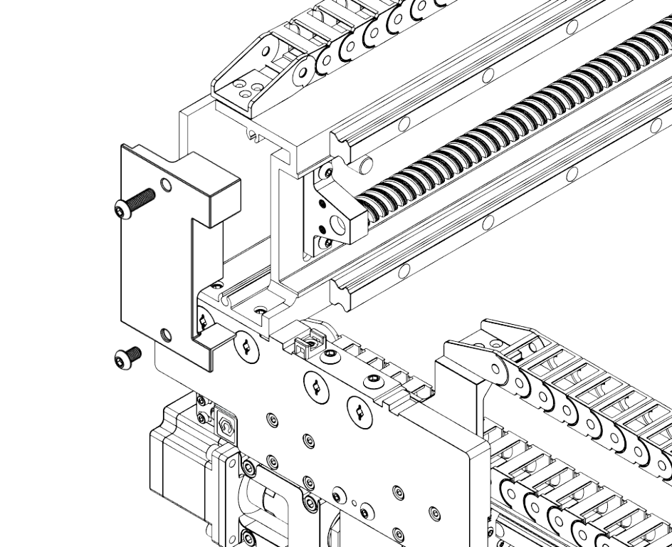
Step 3 - Mount the Air Assist Unit
- Insert the mating plate on the side of the Air Assist Unit to be placed against the spindle mount.
- This guide assumes the Air Assist Unit will be installed on the right side of the spindle mount.
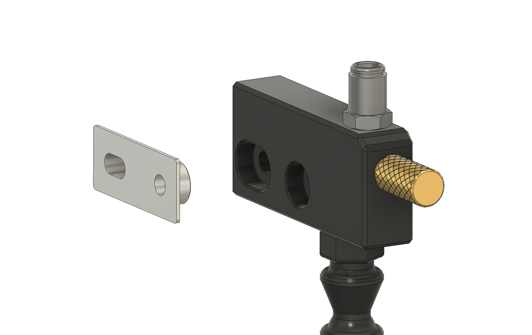
- Affix the Air Assist Unit to the side of the spindle mount.
- Two M5x20 screws go through the body of the Air Assist Unit and secure into the spindle mount.
- Push the air supply tubing into the 6mm fitting on the Air Assist Unit.
- Use cable ties to secure the tubing to the spindle power cable to clean up the installation.
- Ensure there is adequate slack to prevent the spindle power cable and airline from being snagged or strained as the Z-axis moves up and down.
Step 4 - Connect to Shop Infrastructure
- The free end of the 6mm tubing should be connected to your air supply via an air regulator.
- A 6mm push-to-connect fitting with a 1/4" NPT threaded end is supplied for convenience.
Usage
The brass knob on the front of the Air Assist Unit controls airflow. Turn the knob counterclockwise to increase flow and clockwise to reduce flow.
While the adjustment knob is able to restrict airflow to nearly zero, if minimizing leakage is important, an alternate shutoff mechanism (e.g., valve, quick disconnect) should be utilized in line with the Air Assist Kit.
The nozzle of the modular hose should be directed at the cutting portion of an endmill at a 45 degree angle or steeper for the greatest ability to blow debris out of a cut channel.
Modular Hose
By default, 30cm of modular hose is supplied. This can be shortened if required. With the unit off the machine, the hose segments can be pulled apart, removed, and/or pushed back together. If excessive resistance is encountered, gently warming the modular hoses with a heat gun can reduce the force needed to separate or join segments.