This is a guest post by Bob Warfield, founder of the popular CNCCookbook blog and author of G-Wizard, the leading feeds and speeds calculator.

In this multi-part series of guest posts, I want to walk you through the basics of feeds and speeds.
There’s a lot to know, many special cases, and many ways to optimize your CNC work further than the basics will take you. But, with a solid grounding in the basics, you’ll be able to go about your projects with reasonable tool life and surface finishes.
You’ll understand the more common terminology that crops up constantly. And hopefully, I can give you some insights into how all this fits together so you’ll start to have good instincts about Feeds and Speeds.
If you want to know more after we’ve finished, CNCCookbook has a very in-depth Free Feeds and Speeds Course that’ll be a great resource for you.
For this week’s installment, we’re going to talk about the “Speeds” portion of the Feeds and Speeds combo. Speeds refers to your spindle rpm. Determining the correct Speeds for a job is largely a question of determining how fast the tool can be spun without overheating it in the material you’re cutting.
Once a tool overheats, it softens (well short of melting), and this causes the sharp edge to dull. It doesn’t have to get very dull before the tool is done. If you keep going with a dull edge, you’re likely to break the tool, but you’ll see a very deteriorated surface finish before that happens.

Surface Finish, BTW, is what CNC’ers call the tool marks and other irregularities in a surface that’s just been machined. It’s one of three things you have an opportunity to optimize by having proper feeds and speeds. In general, you’re trying to achieve:
Speeds certainly affects Tool Life as we’ve discussed. There is a simple rule of thumb CNC’ers use to determine whether Tool Life problems are due to bad Speeds or bad Feeds:
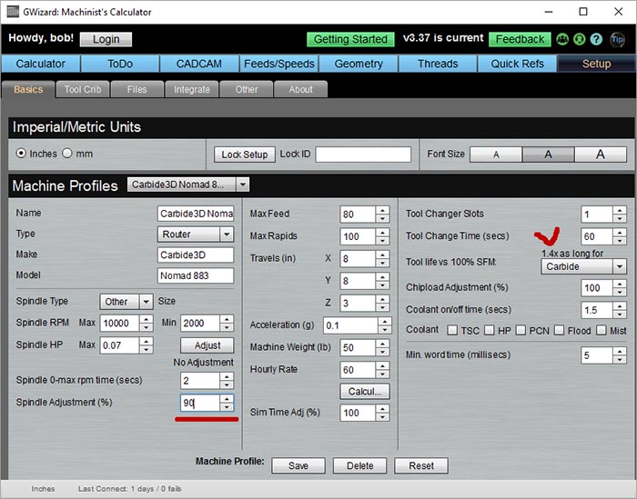
It turns out you there’s something called Taylor’s Tool Life Equations that let you estimate the impact of slowing your speeds on Tool Life. Our G-Wizard Calculator has a Taylor Calculator built right in:

The screen shot is the machine setup page. I’ve marked the Taylor Calculator in red. You can set a permanent reduction (or increase) in spindle speed and G-Wizard will multiply its recommendation by the percentage you specify. In this case, it’s set up to run at 90% of recommended. If we look on the right, there is a dropdown to specify the tool material (calculations differ for HSS vs Carbide tools) and we learn that just by reducing our speed by 10% we get 1.4x longer tool life.
That’s pretty good savings!
A little bit goes a long way, so I wouldn’t take the spindle speed down too much.
We’ve seen how slowing down speeds can increase Tool Life quite substantially. But what’s the right speed for a job? That’s determined by a few factors:
For beginners, #1 and #2 are the main things. Be conservative with those and your jobs will go fine. #3 is more about how to push the envelope successfully or machine really nasty tough materials.
If you want to learn all that, try the course I mentioned. Or, get yourself a good feeds and speeds calculator like G-Wizard and let it worry about it.
To find out how fast a cutter can go in a particular material (assuming you don’t have a feeds and speeds calculator), use a manufacturer’s tooling catalog for recommendations. Or, use Carbide3D’s new charts that are made and tested for their machines.
Here’s a tip: when you stop the spindle at the end of a job, the tool should not be hot. It’ll be lukewarm at best and you can easily touch it with your finger (be careful!). If it is blistering, somethings wrong. It may be too many rpm, or it may be a bad combination of feeds and speeds are causing rubbing. We’ll talk more about rubbing next installment, but suffice to say that if things are working right, most of the heat will be carried away in the chips that are sliced off the material.
Apollo has thoughtfully set up Carbide3D’s feeds and speeds charts with rpms. But, the rpms are only good for one particular tool diameter. If you prowl tooling catalogs looking for feeds and speeds, what you’ll find is they suggest a “Surface Speed” for each cutter and material combination. The advantage of Surface Speed is that it is independent of the tool’s diameter.
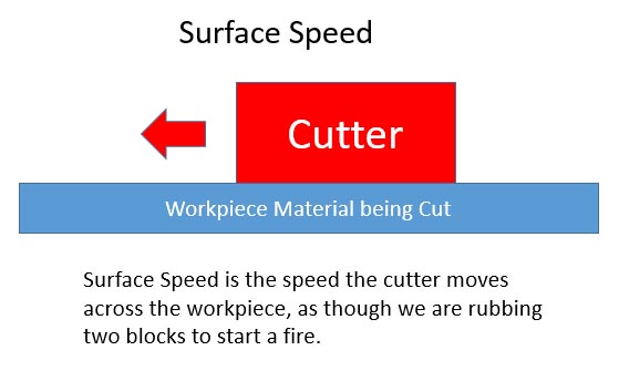
Here’s the notion behind Surface Speed:

Imagine two blocks, one is your cutter, the other is the workpiece. If we slide them together, as though rubbing to start a fire, we get friction and heat. The faster we slide, the more heat. Now imagine an endmill with its spiral helix cutting edges. The proper Surface Speed for a cut is the speed that is as fast as we can go without generating so much heat that our cutter will soften.
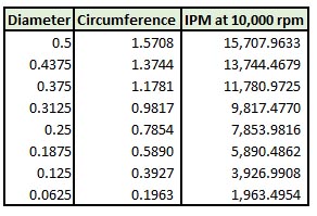
As it spins, it rubs those cutting edges along the workpiece just like the two blocks. If we view it from the end, as a disk, we see that at a given rpm, each diameter has a different surface speed:

For a given spindle rpm, Surface Speed is proportional to diameter. The 1/16″ cutter at bottom is moving 8x slower than the 1/2″ cutter at top. But, for each material and cutter combination, there is only one Surface Speed recommendation. So, we perform a simple calculation with the surface speed and the cutter diameter to determine the proper rpms to hit that Surface Speed.
That’s a good introduction to Speeds. Next installment, we’ll talk about Feeds. As you’ve probably guessed, particularly when I alluded to “rubbing” above, it takes a harmonious combination of both Speeds and Feeds to achieve good results.
See you soon for Feeds!
We'll keep you up to date on new things in the world of Carbide 3D, and CNC in general.